- 您现在的位置:买卖IC网 > Sheet目录1991 > CS4392-KZZ (Cirrus Logic Inc)IC DAC 24BIT 192KHZ W/VC 20TSSOP
CS4392
DS459PP3
11
3.6
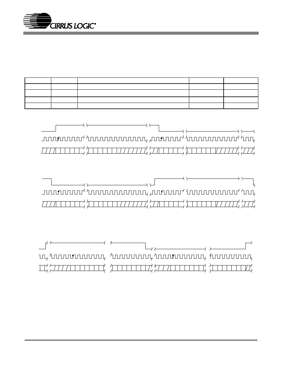
Digital Interface Format
The device will accept audio samples in several digital interface formats as illustrated in Tables 5 and 8.
The desired format is selected via the M0 and M1 pins for stand alone mode, and through the DIF2:0 bits
in the control port. For an illustration of the required relationship between the Left/Right Clock, Serial
Clock and Serial Audio Data, see Figures 4-6.
M1
M0
DESCRIPTION
FORMAT
FIGURE
00
Left Justified, up to 24-bit data
01
I2S, up to 24-bit data
10
Right Justified, 16-bit Data
11
Right Justified, 24-bit Data
Table 5. Digital Interface Format, Stand-Alone Mode Options
Figure 4. Format 0, Left Justified up to 24-Bit Data
LR C K
SC L K
Left C h a n n e l
R igh t C h ann e l
SD A T A
+3 +2 +1 LS B
+5 +4
MSB -1 -2 -3 -4 -5
+3 +2 +1 LS B
+5 +4
MS B -1 -2 -3 -4
Figure 5. Format 1, I2S up to 24-Bit Data
LR C K
SC L K
Le ft C h a n nel
Rig h t Ch a n n e l
SD A T A
+3 +2 +1 LSB
+5 +4
MSB -1 -2 -3 -4 -5
+3 +2 +1 LSB
+5 +4
MSB -1 -2 -3 -4
LRCK
SC LK
Left C hannel
SD ATA
+5 +4 +3 +2 +1 LSB
MSB-1 -2 -3 -4 -5
32 c lo ck s
R ight C h a nnel
LSB
+5 +4 +3 +2 +1 LSB
MSB -1 -2 -3 -4 -5
+6
-6
+6
-6
Figure 6. Format 2, Right Justified 16-Bit Data
Format 3, Right Justified 24-Bit Data
Format 4, Right Justified 20-Bit Data. (Available in Control Port Mode only)
Format 5, Right Justified 18-Bit Data. (Available in Control Port Mode only)
发布紧急采购,3分钟左右您将得到回复。
相关PDF资料
CS4397-KSZ
IC DAC 24BIT MULTY STNDRD 28SOIC
CS4398-CZZ
IC DAC 120DB 192KHZ W/VC 28TSSOP
CS43L22-CNZR
IC DAC W/HDPN & SPKR AMPS 40-QFN
CS4461-CZZR
IC ADC PSR FEEDBACK 24-TSSOP
CS5340-CZZ
IC ADC AUD 101DB 200KHZ 16-TSSOP
CS5340-DZZR
IC ADC AUD 101DB 200KHZ 16-TSSOP
CS5341-DZZ
IC ADC AUD 105DB 200KHZ 16-TSSOP
CS5342-CZZ
IC ADC AUD 105DB 200KHZ 16-TSSOP
相关代理商/技术参数
CS4392-KZZR
功能描述:数模转换器- DAC IC 114dB 192kHz Stereo DAC w/DSD RoHS:否 制造商:Texas Instruments 转换器数量:1 DAC 输出端数量:1 转换速率:2 MSPs 分辨率:16 bit 接口类型:QSPI, SPI, Serial (3-Wire, Microwire) 稳定时间:1 us 最大工作温度:+ 85 C 安装风格:SMD/SMT 封装 / 箱体:SOIC-14 封装:Tube
CS4396
制造商:CIRRUS 制造商全称:Cirrus Logic 功能描述:24-Bit, 192 kHz D/A Converter for Digital Audio
CS4396-KS
功能描述:数模转换器- DAC 24Bit 192 kHz DAC for Digital Audio RoHS:否 制造商:Texas Instruments 转换器数量:1 DAC 输出端数量:1 转换速率:2 MSPs 分辨率:16 bit 接口类型:QSPI, SPI, Serial (3-Wire, Microwire) 稳定时间:1 us 最大工作温度:+ 85 C 安装风格:SMD/SMT 封装 / 箱体:SOIC-14 封装:Tube
CS4396-KSR
功能描述:数模转换器- DAC 24Bit 192 kHz DAC for Digital Audio RoHS:否 制造商:Texas Instruments 转换器数量:1 DAC 输出端数量:1 转换速率:2 MSPs 分辨率:16 bit 接口类型:QSPI, SPI, Serial (3-Wire, Microwire) 稳定时间:1 us 最大工作温度:+ 85 C 安装风格:SMD/SMT 封装 / 箱体:SOIC-14 封装:Tube
CS4396-KSZ
功能描述:数模转换器- DAC IC 24Bit 192 kHz DAC for Digital Audio RoHS:否 制造商:Texas Instruments 转换器数量:1 DAC 输出端数量:1 转换速率:2 MSPs 分辨率:16 bit 接口类型:QSPI, SPI, Serial (3-Wire, Microwire) 稳定时间:1 us 最大工作温度:+ 85 C 安装风格:SMD/SMT 封装 / 箱体:SOIC-14 封装:Tube
CS4396-KSZ
制造商:Cirrus Logic 功能描述:D/A Converter (D-A) IC
CS4396-KSZR
功能描述:数模转换器- DAC IC 24Bit 192 kHz DAC for Digital Audio RoHS:否 制造商:Texas Instruments 转换器数量:1 DAC 输出端数量:1 转换速率:2 MSPs 分辨率:16 bit 接口类型:QSPI, SPI, Serial (3-Wire, Microwire) 稳定时间:1 us 最大工作温度:+ 85 C 安装风格:SMD/SMT 封装 / 箱体:SOIC-14 封装:Tube
CS4397
制造商:CIRRUS 制造商全称:Cirrus Logic 功能描述:24-Bit, Multi-Standard D/A Converter for Digital Audio